Cooling System Basics
For a more detailed look at the cooling system, visit the Cooling Bible on BillaVista.com.
Common Misconceptions
- Coolant temperatures are not an accurate indicator of metal temperatures. The coolant's maximum temperature is its pressure corrected vapor point. The metal can be several hundred degrees hotter than the adjacent coolant.
- Temperatures of critical areas must be determined by checking the metal at a controlled distance from the combustion chamber surface. This eliminates discrepancies caused by the variances in metal thicknesses.
- Higher coolant flow will ALWAYS result in higher heat transfer. Coolant cannot absorb heat after it reaches its pressure corrected vapor point. Furthermore, coolant absorbs heat at a progressively slower rate as it approaches this point.

Energy Loss
- Spark ignition engines lose almost 33% of their energy input through the cooling system.
- Energy loss is very simple to calculate on the dyno or the vehicle. All you need is the inlet coolant temperature, outlet coolant temperature, coolant flow and the specific heat of the coolant.
Following is a typical engine:
- Inlet temperature = 180 F
Outlet temperature = 190 F
Coolant flow = 100 GPM
Specific heat of coolant = 1.0
1 HP = 5.2769885 GPM 1 F
{ (Outlet-Inlet)CS} / 5.2769885 = HP loss
{(190-180) 100*1.0} / 5.2769885 = 189.5 H
Basic Functions of the Cooling System
- Peak temperature in the combustion chamber is in excess of 5000 F. Aluminum melts at 1220 F, Iron at 1990-2300 F. Therefore, the obvious primary function of the cooling system is the prevention of component damage.
- However, spark ignition (SI) engines experience pre-ignition and subsequent detonation at temperatures much lower than those resulting in component failure.
- Poor cooling system performance results in component damage in SI engines but, this damage is a result of pre-ignition/detonation. Not the temperature alone.
- This secondary function of controlling pre-ignition/detonation is actually the most important in the SI engine.

Engines
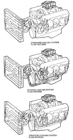
- On traditional flow configurations the block is pressurized by the water pump and functions as a manifold. The head gasket distributes the coolant through its orifices. Block pressure must be consistent from front to rear to insure uniform coolant distribution. Low pressure will result in less flow around the rear cylinders.
- Reverse flow systems pressurize the cylinder heads and bleed off through the block. Coolant gains only 1-2 F as it goes through the block. Reverse flow decreases the temperature of the coolant through the cylinder heads by this amount. The fact that steam rises complicates reverse flow systems and generally makes the 1-2 F reduction in coolant temperature insignificant at best.
- The flow through each orifice in the head gasket can be determined by measuring the pressure drop across each orifice while coolant is being forced through the engine.
- Coolant flow has a direct relationship to area and an exponential relationship to pressure. Meaning that when you double the area of an orifice and maintain pressure the flow doubles, but when you double the pressure and maintain area the flow is only increased by 1.414 (the square root of 2).
- Strategic Flow systems take advantage of the knowledge gained through flow mapping. 100% of the coolant flow crosses the critical exhaust seat area first and is then distributed according to need to the other areas of the engine. Coolant is taken from the highest point thus eliminating the pitfalls of reverse flow systems.

Radiators
- The most important criteria for any radiator is its surface area. The thickness of the core is increased only after the surface area is maximized. Adding thickness to a radiator does not increase its efficiency the same extent as surface area, but in no case will additional thickness alone decrease the efficiency.
- The radiator becomes less efficient as the coolant outlet temperature approaches ambient. Therefore, a low flow rate keeps the coolant in the radiator longer. The longer the coolant stays in the radiator the lower the efficiency of the radiator.
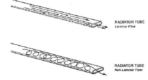
- Non-laminar or turbulent coolant flow must be maintained within the radiator core.
- When baffles are inserted in the tanks to force the water to go through the radiator twice, the water spends the same amount of time in the radiator but must go twice the distance. Thus doubling the speed of the water.
- Crossflow radiators with a fill cap always have the cap on the outlet side. Upright radiators have the cap in the inlet side and thus subject the filler cap to the pressure drop of the radiator's core in addition to the system pressure. This can lower the effective pressure of a 22 PSI cap to as low as 10 PSI.
- Thermostat housing restrictors were useful when upright radiators were used with 7 lb. caps. The restrictor slowed the flow and kept the pressure in the radiator down. This prevented the cap from expelling water and causing the car to overheat. Most people wrongly assumed the car ran hot and expelled water. The cars actually expelled water and ran hot.
Hoses
- Large diameter hoses with large radius bends should be used. Never use braided hoses, they will always result in higher metal temperatures.

Pressure
- Higher system pressures raise the vapor point of the coolant and subsequently its ability to absorb heat. A system pressure of 12-17 PSI results from the expansion of the coolant and trapped air going from ambient temperature to operating temperature.
- The system achieves this pressure only when the system is filled cold. When a warm system is opened and resealed this pressure is not obtainable because the coolant and trapped air are already expanded when the system is sealed.
- A Schrader valve installed in the system will allow the system to be charged by an air hose. This allows an already warm system to achieve operating pressure and minimizes the effect of trapped air in a cold system.
- The fill cap must be the highest point of the system. Surge tanks must be used if the top of the radiator is not the highest point.
- Trapped air seeks the highest point. A new system always has trapped air. Always fill the surge tank completely, when the system reaches operating temperature it will expel any excess water out of the overflow.
- Placing a fill cap in the top radiator hose subjects the cap to the pressure drop of the top hose and the radiator core in addition to the system pressure. This can lower the effective pressure of a 22 PSI cap to as low as 2 PSI.
The vapor point of water increases under pressure as follows:
- 10 PSIG = 239° F
- 20 PSIG = 259° F
- 30 PSIG = 273° F
- 40 PSIG = 286° F
- 50 PSIG = 297° F
- 60 PSIG = 307° F
- 70 PSIG = 316° F
Always use the highest pressure cap available. It merely serves as a safety valve that has no function when the system is operating properly.
Coolant
- 1 BTU is the amount of energy required to raise 1 pound of water 1° F. Of all common liquids water requires the most energy to accomplish this. Therefore water has a specific heat of 1°. An Ethylene Glycol/water mix has a specific heat of 0.5, meaning it requires only 0.5 BTUs to raise the temperature of 1 pound Ethylene Glycol/water mix 1° F. Propylene Glycol has a specific heat of only 0.3.
- On a typical engine with a coolant flow rate of 100 GPM and an energy loss through the cooling system of 189.5 HP, water would need to gain only 10° F, Ethylene Glycol/water mix would gain 20° F, and Propylene Glycol would gain 33.3° F.
- This equation is complicated by the difference in a vapor point of the 3 coolants. Ethylene Glycol and Propylene Glycol have higher vapor points and thus can absorb heat at higher temperatures. However, even with its lower vapor point, water still carries more heat per unit than the others.
Grill Opening
- Radiators have approximately one third open area. The remainder is taken up by the fins and tubes. The maximum functional grill opening equals the open area of the radiator.
- Radiator open area can be calculated by subtracting the area taken up by tubes and fins from the total.
- Grill open area can be calculated by subtracting the area taken up by decorative grill work and the wire mesh from the total.
- The angle of the grill opening complicates the issue because a sloping opening passes less air than a vertical opening.
- Blocking off a sloping grill opening affects the aerodynamic balance much greater than blocking a vertical opening. The entire grill opening should be vertical if at all possible.
Pumps
- Proper bench testing of accessories is the only proper method of development. The accessories affect so many functions of the engine that testing them on a running engine on the dyno is a total waste of effort.
- The coolant pump is a great example of an accessory that must be tested and developed off the engine. To bench test the coolant pump you must know pressure drops at a given flow for all the components of the cooling system.
Following is a typical Winston Cup engine at 100 GPM:
- Lower radiator hose = 1.5 PSI
Block and cylinder head - each (at 50 GPM) = 8.5
Outlet manifolding = 1.25
Top radiator hose = 2.25
Radiator = 1.5
Total = 15.00 PSI
In addition to having the proper flow restriction as expressed in GPM @ PSI the cooling system pressure and temperature must be known. All these conditions are duplicated for the bench test.
Energy losses due to driving the coolant pump can only be calculated when all conditions are duplicated and torque and RPM are measured. Amp draw of the drive motor is not an accurate measure of the energy required to drive the pump. Torque must be measured with a load cell and horsepower calculated from there.
Most pumps are biased to the inlet side. Most even spaced cylinder heads (IE, IE, IE, IE) are biased to the exhaust end.
There are three basic impeller designs: universal, clockwise, and counter clockwise. The directional specific impellers are more efficient that the universal impellers. The performance of all designs are very similar when installed in the same housing.
Metal temperatures always increase when you slow the water pump down.
For a more detailed look at the cooling system, visit the Cooling Bible on BillaVista.com.
CONTACT US
Concept ONE Pulley Systems
6320 Georgia Highway 400
Cumming, GA 30028
1-877-337-0688
infoteam@c1pulleys.com


